Automatic Dosing Siphon Installation Process
Automatic Siphons Installed in Precast Concrete Manhole, 3 Compartment Septic Tank and Concrete Dosing Tank
Standard Installation
Set the siphon trap in concrete, being sure that it is plumb and level and that the long leg of the trap extends above the floor the correct distance (please refer to the drawing). The discharge line from the siphon should be vented back into the dosing tank. An overflow pipe will accomplish this. The overflow pipe and the outlet pipe must be connected to the outlet of the siphon using a gasketed fitting. It is not possible to solvent weld the fitting to the high density polyethylene with which the siphon is constructed. This may be accomplished by using a gasketed 'T' fitting or by a short length of sewer pipe that has a gasketed belled end, and then connecting it to a solvent weld 'T' fitting. The discharge pipe must not run uphill. It can be flat, though it is better to have at least a slight downhill pitch to it to prevent it from backing up.
With the 1/4-20 bolts started into the trap, place the bell over the trap and rotate it till the slots in the collar of the bell line up with the bolts in the trap. Push the bell down and rotate it. Tighten the bolts. Make sure the siphon trap is primed with water. You are now ready to test the siphon.
See the Dosing Siphon Features
Optional Installations
Our instructions show the floor line 3 inches below the bell or the low water line (figure 4). Although this is the standard installation other types of installation will work.
The floor line may be dropped below the outlet of the siphon with the discharge of the siphon run through the side of the tank (figure 5). The entire siphon may be placed in the tank. A pedestal is poured around the siphon trap to hold it secure. The discharge piping is run through the side of the tank (figure 6). The additional depth below the siphon bell (or the low water line) provides additional settling capacity for solids that were not settled out in the first compartment(s) of the tank. If it is ever necessary to work on the siphon, the tank will need to be pumped out before the siphon can be accessed.
It is important that the siphon be held secure, plumb and level; once this requirement is met, it is possible to mount the siphon several different ways.
Dual Alternating Siphons
In dual alternating siphon installations, care must be taken to set both traps at the same elevation. They must both be plumb and level. The siphons must NOT discharge into the same line or an interconnecting line because this will permit the discharge from one siphon to refill the trap of the idle siphon and prevent alternating operation. The siphons may be close together or at opposite ends of the dosing tank. The outlets do not need to be parallel to each other. The discharge lines can be set in any direction, though they must NOT run uphill.
In dual alternating siphon installations, care must be taken to set both traps at the same elevation. They must both be plumb and level. The siphons must NOT discharge into the same line or an interconnecting line because this will permit the discharge from one siphon to refill the trap of the idle siphon and prevent alternating operation. The siphons may be close together or at opposite ends of the dosing tank. The outlets do not need to be parallel to each other. The discharge lines can be set in any direction, though they must NOT run uphill.
Optional Overflow Pipe
The Overflow pipe serves two functions; it vents the siphon to the atmosphere and it provides a safety outlet in the unlikely event the siphon should fail. We believe that the simplest method of installing the overflow is to place a 'T' fitting on the outlet of the siphon and bring it straight up (figure 4). It is acceptable to run the discharge of the siphon to a point just outside of the dosing tank, put a 'T' fitting on at this point, and run the overflow pipe up and through the side of the dosing tank (figure 7).
The Overflow pipe serves two functions; it vents the siphon to the atmosphere and it provides a safety outlet in the unlikely event the siphon should fail. We believe that the simplest method of installing the overflow is to place a 'T' fitting on the outlet of the siphon and bring it straight up (figure 4). It is acceptable to run the discharge of the siphon to a point just outside of the dosing tank, put a 'T' fitting on at this point, and run the overflow pipe up and through the side of the dosing tank (figure 7).
Flow Rates
The flow rates that we publish are free-flow rates. Friction losses or restrictions in the discharge piping will slow the siphon down, but it will still function properly. If it is important to maintain as high a flow rate as possible, the discharge piping should be one size larger than the siphon. For example use 6 inch discharge piping with a 4 inch siphon.
The flow rates that we publish are free-flow rates. Friction losses or restrictions in the discharge piping will slow the siphon down, but it will still function properly. If it is important to maintain as high a flow rate as possible, the discharge piping should be one size larger than the siphon. For example use 6 inch discharge piping with a 4 inch siphon.
Reducing the Siphon Discharge Line
The siphon discharge line may be reduced, but it must be done in a manner that does not raise the essential elevation of the outlet. Most reducing bushings reduce to the center, so that reducing the discharge line of a 4 inch siphon to a 2 inch line right at the outlet would raise the outlet of the siphon an inch, which could cause the siphon to malfunction. In this case, it would be necessary to run 4 inch discharge piping until the line had fallen at least one inch, and only then would the line be reduced to 2 inch (figure 8). An eccentric reducing bushing oriented towards the bottom could be installed without any fall in the outlet. The diameter of the discharge pipe should be at least as large as the diameter of the siphon trap for a minimum of 10 feet past the overflow pipe.
The siphon discharge line may be reduced, but it must be done in a manner that does not raise the essential elevation of the outlet. Most reducing bushings reduce to the center, so that reducing the discharge line of a 4 inch siphon to a 2 inch line right at the outlet would raise the outlet of the siphon an inch, which could cause the siphon to malfunction. In this case, it would be necessary to run 4 inch discharge piping until the line had fallen at least one inch, and only then would the line be reduced to 2 inch (figure 8). An eccentric reducing bushing oriented towards the bottom could be installed without any fall in the outlet. The diameter of the discharge pipe should be at least as large as the diameter of the siphon trap for a minimum of 10 feet past the overflow pipe.
Handling Dips in the Discharge Line
A dip in the discharge line can create a water trap, which may significantly slow the flow rate of the siphon. Air becomes trapped between the water trap created by the dip in the discharge line and the rapid flow of effluent from the siphon. The air must fight up the flow of water from the siphon to the siphon overflow pipe to escape. If it is impractical to avoid having a dip in the discharge line, we recommend using a larger discharge pipe than the siphon trap (use 6 inch or 8 inch pipe with a 4 inch siphon). Another method to maintain the flow rate would be to vent the discharge line to the atmosphere right before the dip.
A dip in the discharge line can create a water trap, which may significantly slow the flow rate of the siphon. Air becomes trapped between the water trap created by the dip in the discharge line and the rapid flow of effluent from the siphon. The air must fight up the flow of water from the siphon to the siphon overflow pipe to escape. If it is impractical to avoid having a dip in the discharge line, we recommend using a larger discharge pipe than the siphon trap (use 6 inch or 8 inch pipe with a 4 inch siphon). Another method to maintain the flow rate would be to vent the discharge line to the atmosphere right before the dip.
Drawing Depth
The drawing depth of the siphon (the distance between the high water line and the low water line) is not readily adjustable. Although we have modified the drawing depth of installed siphons, it is usually difficult and expensive and there are limitations. We can manufacture custom siphons with special drawing depths on request. It is much easier and more cost effective to order a special siphon rather than modifying one in the field. It is frequently less expensive to purchase a custom siphon than a custom tank. There are minimum drawing depths required to make a siphon operate and these vary according to the size of the siphon. There is virtually no maximum limit to the drawing depth. The siphon can be manufactured in any diameter. We have manufactured numerous custom siphons with a wide range of sizes and drawing depths. Please call us for a free quotation on a custom siphon.
Handling Raw Sewage
The standard Automatic Dosing Siphon is not designed to handle raw sewage. The solids in raw sewage will clog the vent pipes and cause the siphon to fail. We have built siphons modified with two or three inch diameter vent pipes to handle raw sewage. The siphon must be at least a 5" diameter siphon or larger. The flow rates will be somewhat slower than a standard siphon because the larger inside vent pipe will reduce the effective diameter of the siphon trap. It may be necessary to use a larger siphon to compensate for this.
Plural Alternating Siphons
You can direct the flow of discharge from a dosing tank to alternate between different absorption fields by placing more than one siphon in a single dosing tank.
Two siphons placed in the same tank at the same elevation will alternate automatically without the need for any additional equipment.
Electrically-Controlled Siphons
If electrical power is available at the site, an alternating solid state relay system can be used to sequence 3, 4, or 6 siphons. The relays control a small solenoid air valve attached to each siphon. Opening the solenoid air valve on a siphon will start that particular siphon. Relay controlled siphon systems may be powered by solar recharged batteries.
By using a personal computer to control the solenoid air valves, up to 32 siphons may be sequenced. Siphons are an inexpensive and reliable substitute to large solenoid controlled valves.
The current drawn by the electrical alternating siphons is minimal, and much less than the current drawn by pumps. In addition, the components are inexpensive and easy to replace.
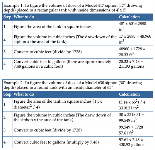
Determining the Volume of Liquid Dosed by the Siphon
The volume of liquid dosed by the siphon is a function of the area of the tank and the drawing depth of the siphon.